
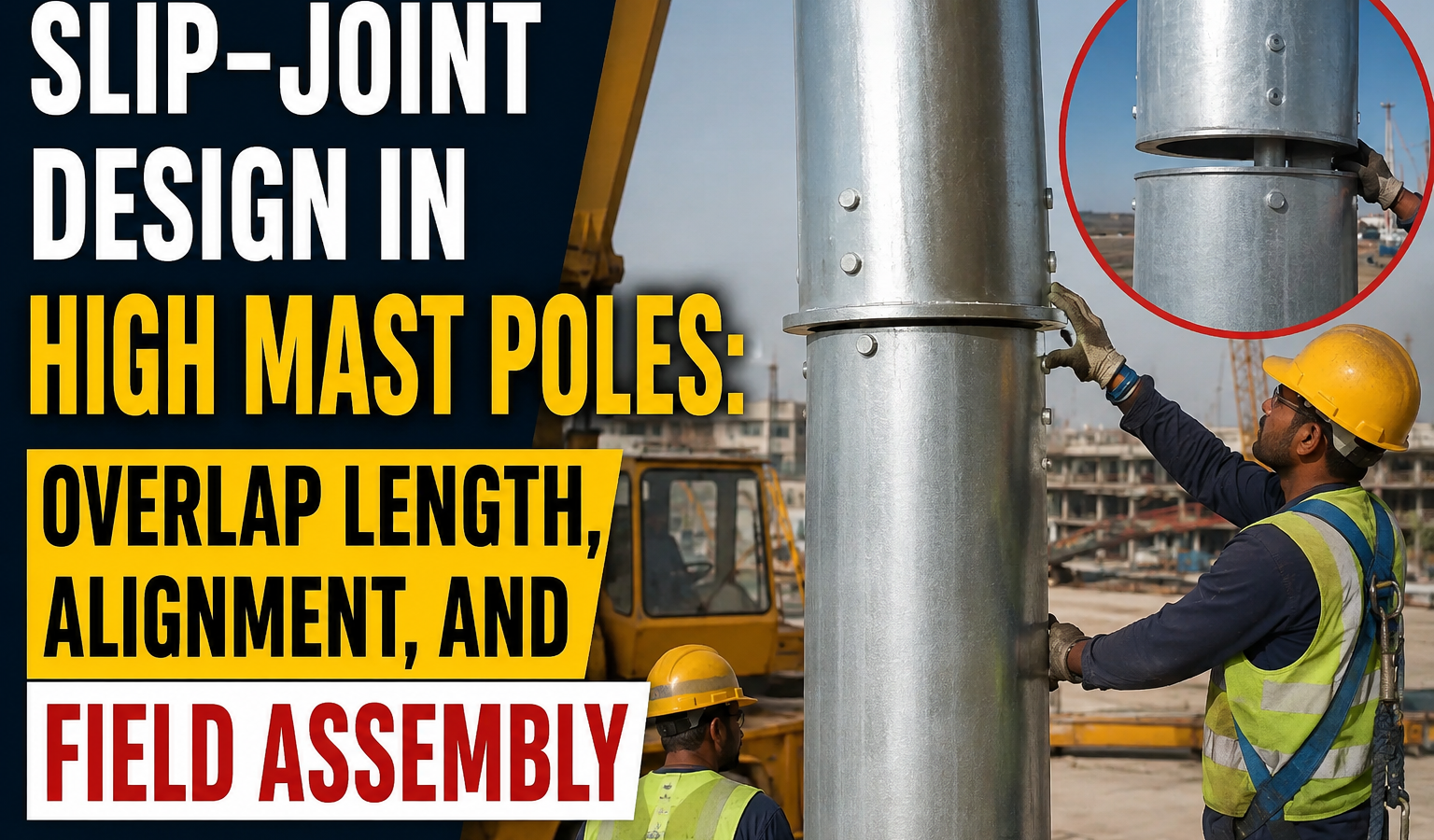
Multi-section high mast poles rely on friction, not fasteners, to hold their field joints together. The slip-joint — a telescopic overlap where one taper section is driven into the next — is the single most misunderstood connection in high mast engineering. Get the overlap length wrong and the joint either slips under load or locks so tight it can’t disassembl for maintenance decades later Slip-Joint Design in High Mast Poles.
This article covers the engineering formula behind overlap length, factory alignment marking, why field welding at this joint is almost always prohibited, and the practical erection sequence that determines whether a slip-joint performs as designed for the life of the structure.
Slip-joint performance is also one of the few high mast design elements that’s genuinely difficult to inspect once the structure is standing — unlike a weld or a coating thickness, which can be checked visually or with a gauge at any point, a slip-joint’s actual interference fit and friction capacity are effectively locked in at the moment of erection and rarely re-verified afterward. That makes getting the design, the factory marking discipline, and the erection procedure right the first time considerably more important than it might be for a component with easier ongoing inspection access.
The Engineering Formula Behind Minimum Telescopic Overlap
Slip-joint overlap length is govern friction-grip theory, not arbitrary rule-of-thumb. The widely referenced design guidance (drawn from AASHTO practice and adopted in most Indian high mast specifications) sets minimum overlap as: Overlap length (L) = 1.5 × D, where D is the average diameter (or the across-flats dimension for polygonal sections) at the joint, with an absolute minimum overlap of 300mm regardless of pole diameter.
Some specifications tighten this further to 1.5D but not less than 400-450mm for masts above 20m, because the friction capacity of the joint must exceed the peak bending moment transferred at that splice location under design wind load, with a safety margin against long-term relaxation of the interference fit as the galvanized surfaces bed in over repeated thermal cycling Slip-Joint Design in High Mast Poles.
The underlying mechanics are worth understanding rather than just applying as a formula: the joint transfers moment through a couple of compressive contact forces distributed along the overlap length, acting on opposite flats or opposite sides of the taper. A longer overlap spreads this contact force over more surface area, reducing local contact pressure and the associated risk of galling or fretting at the interface — a longer overlap is therefore not just a bigger safety margin on paper, it changes the actual contact mechanics for the better.
Why Splice Location Along the Mast Matters
Overlap length calculations are typically govern the diameter at the specific splice location, not a single value for the whole pole — a 30m mast might have splice joints at roughly one-third and two-thirds height, each with a different local diameter and therefore a different require overlap. Engineers reviewing shop drawings should check that the overlap shown at each individual splice satisfies 1.5× the diameter at that specific location, not a single blanket dimension copied across all joints.
Factory Alignment Marking for Field Slip-Jointing
Because a taper polygonal section has a specific rotational orientation that must match its mating section — facet-to-facet, not just diameter-to-diameter — every slip-joint pair is factory-match and mark, typically with paint-stripe alignment marks or stamp match-marks (e.g., ‘A-A’, ‘B-B’) on adjoining sections before they ever leave the fabrication shop.
This match-marking exists because the male (upper) section’s facets must sit flush inside the female (lower) section’s facets; a rotational mismatch of even a few degrees creates point-loading along facet edges instea of full-surface friction contact, drastically reducing joint capacity and concentrating stress exactly where the joint is meant to distribute it evenly.
In practice, match-marking discipline breaks down most often during transport and storage — sections get stack, moved between yards, or re-sort at site without care for maintaining pairs together, and marks fade or get scrap off during handling. A rigorous fabricator will duplicate match-marks in more than one location on each section (e.g., both near the joint edge and further up the section body) specifically so at least one mark survives transport and handling damage.
Is On-Site Welding Permitted at the Slip-Joint?
No — virtually every high mast specification prohibits field welding at the slip-joint interface. The joint is design as a pure friction-fit connection, engineer through controlled interference (typically an oversize of 1.5-3mm on the diameter, achieve via the calculate taper geometry) and seat using calibrate hydraulic force, not heat.
Field welding would compromise the hot-dip galvanized coating at precisely the point of highest stress concentration, introduce an uncontrolled heat-affected zone into a friction joint never designed to carry a weld, and eliminate any possibility of future disassembly for maintenance or section replacement — a real operational need, since a damaged tip section or headframe sometimes needs replacement without discarding the entire pole.
Where site crews have historically resorted to tack-welding a slip-joint — usually out of concern that friction alone ‘looks insufficient’ during erection — this should treate as a red flag for inadequate erection procedure training rather than accommodat as an acceptable field practice. The correct response to a joint that doesn’t seat properly is to investigate overlap length, interference fit, or jacking force, not to weld around the problem.
Erection Sequencing and Joint Seating Verification
Beyond the joint geometry itself, the erection sequence used to close a slip-joint materially affects its final performance. Most specifications call for the mating sections to align, lightly seat controlled lowering via crane, and then driven to final interference fit using a hydraulic ram or calibrate drop-hammer arrangement acting through a purpose-built driving cap that protects the tip edge of the section from local damage during the seating operation.
Verifying that a joint has actually reached its design interference fit — rather than merely looking seated — typically relies on a combination of measured travel distance (the overlap length achieved should match the calculated design value within tolerance) and a qualitative check of resistance during the final seating passes, where a properly interfering joint shows a distinct increase in required driving force as it approaches full seating, while a joint seating too easily throughout may indicate insufficient interference and warrants investigation before the crew moves to the next section.
Erection crews unfamiliar with high mast-specific procedures sometimes default to techniques borrowed from simpler pole types, underestimating both the required jacking force and the precision needed in alignment before driving begins. Pre-erection training specific to the slip-joint system being use— ideally including a supervise trial assembly of the first pole on a given project — meaningfully reduces the risk of an improperly seat joint being miss and left in a field structure.
Practical Field Best Practices
- Never accept a slip-joint overlap below 1.5D or the specification’s stated minimum, whichever governs.
- Verify match-marks are legible after galvanizing — re-mark with paint if zinc dipping obscures factory stamps.
- Confirm the erection crew is using the specified hydraulic jacking force, not free-fall or hammer-seating, to close the joint.
- Flag any as-built drawing showing field welds at a slip-joint for immediate engineering review.
- Duplicate match-marks in two locations per section to survive transport and handling wear.
- Verify overlap length independently at each splice location, not assuming a single blanket dimension throughout Slip-Joint Design in High Mast Poles.
Summary Checklist
- Overlap length ≥ 1.5D (or spec minimum ~300-450mm) at every splice location.
- Factory match-marks present and legible on both mating sections.
- Zero field welding at the telescopic joint — friction-fit only.
- Interference fit achieved via calculated taper, not forced oversizing on site.
- Match-mark redundancy checked for sections that traveled long distances to site.
- Erection crew trained on calibrated jacking procedure, not improvised seating methods.