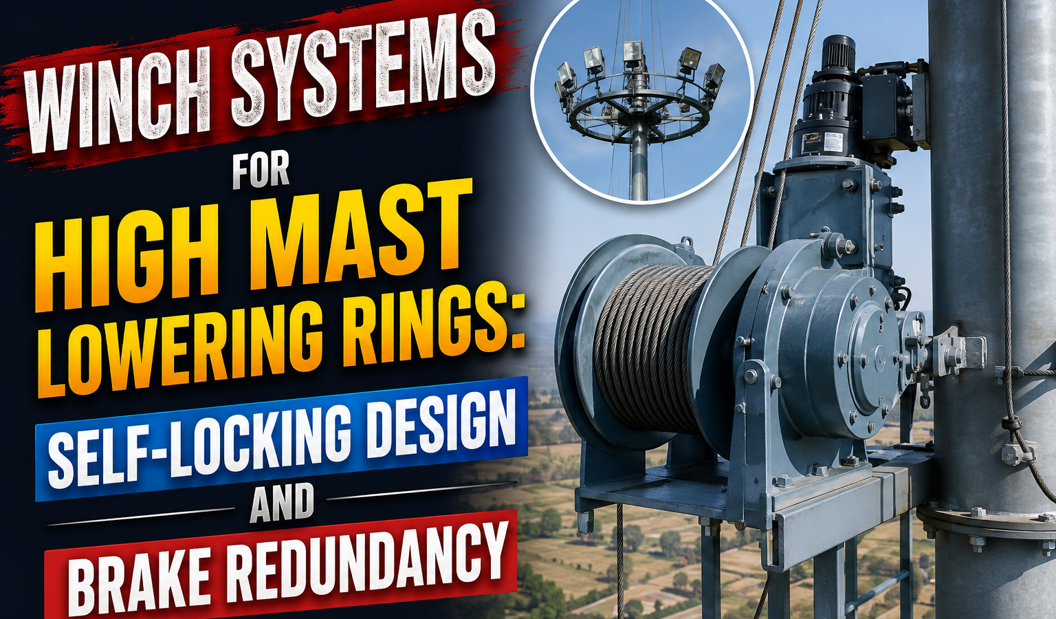
Every high mast lowering-ring system hangs its safety case on one mechanical assumption: the winch will not release the load if power or a component fails. Unlike most lifting equipment that operates briefly and under supervision, a high mast winch holds a luminaire ring aloft continuously for months between maintenance cycles, with no operator present to react to a developing fault High Mast Lowering Rings.
This section explains why worm-and-wheel winches dominate this application, what redundancy exists if the primary brake fails, and how rated load capacity should compare to actual ring dead weight — three separate safety layers that together define whether a system is genuinely fail-safe or merely fail-unlikely.
It’s worth framing why this component receives disproportionate engineering attention relative to its size and cost within the overall high mast system: unlike a structural weld or a foundation, whose failure modes tend to develop slowly and give some warning through visible cracking or settlement, a winch or brake failure can be sudden and essentially without warning to anyone at ground level. That risk profile — low probability but high and immediate consequence — is precisely what justifies the layered, redundant safety philosophy this section describes, even though it adds cost and complexity relative to a simpler single-brake design.
Self-Locking Worm-and-Wheel Winch Design
Almost universally, high mast lowering-ring winches use a worm-and-wheel gear configuration precisely because it is inherently self-locking — the worm’s low lead angle means the wheel cannot back-drive the worm under load, regardless of motor state. This is a passive, geometry-based safety feature, not something dependent on a brake being engaged, a control system functioning, or power being available at all.
This self-locking behaviour means that even in a total power failure with the manual handle disengaged, the ring simply stays where it is — it cannot free-fall through the gearbox, because the physics of the gear mesh itself prevents reverse-driving rather than relying on any actively controlled component to intervene.
It’s worth noting that not all worm-and-wheel combinations are equally self-locking — the lead angle of the worm thread determines the degree of self-locking, and a poorly designed or heavily worn worm gear with a shallow, high-efficiency thread profile can lose some of this inherent safety margin over years of service. This is one of several reasons why periodic winch inspection (checking for backlash, wear pattern on the worm thread, and gearbox oil condition) remains part of a properly run maintenance program rather than a one-time installation check.
Mechanical Redundancy: What Stops the Ring If the Primary Brake Fails?
Despite the inherent self-locking of the worm gear, specifications for high mast winches still require a secondary mechanical safety — commonly a mechanical pawl-and-ratchet or a spring-applied disc brake on the motor/gearbox input shaft, independent of the worm gear’s self-locking property. This layered approach follows standard lifting-equipment design philosophy: no single safety feature, however reliable in principle, should be the sole barrier against a dropped load.
Some systems add a secondary independent safety device entirely outside the winch/rope load path — such as a mechanical locking collar at the headframe (see Cluster 10) that physically engages when the ring reaches full-up position, removing tension from the wire rope and winch altogether during normal illuminated operation. This is a meaningfully different kind of redundancy: it doesn’t just duplicate the winch’s holding function, it removes the winch from the load path entirely for the vast majority of the structure’s operating life, since the ring typically only relies on the winch and rope during the brief raising/lowering operation itself.
Why Redundancy Philosophy Matters for Procurement
High Mast Lowering Rings, Procurement specifications sometimes list ‘self-locking winch’ and ‘mechanical brake’ as though they were two ways of describing the same feature — they are not. A genuinely redundant design has two independent mechanisms that would each, on their own, prevent an uncontrolled drop, such that a single component failure (whether in the gear, the brake, or the control system) still leaves one functioning safety layer. Evaluating a technical bid should specifically ask the vendor to describe the failure mode of each safety mechanism independently, rather than accepting a general assurance that the system is ‘fail-safe.’
Rated Load Capacity vs. Ring Dead Weight
Winch rated capacity is specified against the fully-loaded ring dead weight (luminaires, brackets, wiring, ring structure) with a safety factor — commonly a minimum of 4:1 to 5:1 on the winch and wire rope system, consistent with lifting equipment design margins rather than simple structural margins, which typically run closer to 1.5:1-2:1.
This means a ring assembly weighing, for example, 150-200kg fully loaded should be paired with a winch and rope system rated well above 750-1000kg working load limit, not sized to the dead weight alone. The higher margin reflects both the dynamic loading that occurs during raising and lowering (acceleration and deceleration effects, occasional snagging or binding during travel) and the progressive capacity loss a winch and rope system experiences through normal wear over its service life.
A practical procurement check: ask for the winch nameplate rated capacity and the rope’s minimum breaking load independently, then verify both against the actual measured (not estimated) ring weight — some fabricators quote winch capacity based on the rope’s rating alone without confirming the gearbox and brake are matched to the same capacity, creating a mismatch where the weakest link in the chain isn’t the one everyone assumes.
Commissioning Load Testing and Documentation
Rated capacity on a nameplate is a design intent, not a verified fact for the specific unit installed — which is why commissioning load testing, typically at 100-125% of the actual expected working load rather than the winch’s full rated capacity, is standard practice before a lowering system is hand over for operational use. This test confirms the assembled system (winch, gearbox, brake, rope, and headframe pulleys together) performs as an integrated unit, since bench-testing individual components in isolation doesn’t guarantee they interact correctly once installed.
Documentation from this commissioning test — load applie, hold time, any observ creep or slippage, and sign-off from a qualified inspector — should become part of the permanent asset record for that specific pole, the same way structural certificates and MTCs are retain. When a maintenance dispute or incident investigation arises years later, this record is often the only objective evidence of how the system actually performed at handover, as opposed to how it was merely specified to perform.
For large multi-mast contracts, some owners specify a sampling regime — full commissioning load test on every unit versus a statistically representative sample — as a way to balance thoroughness against cost and schedule; either approach is reasonable provided it’s a deliberate decision documented in the contract rather than commissioning testing being skipped altogether under time pressure.
Practical Field Best Practices
- Confirm the winch is a genuine self-locking worm-and-wheel type — not a spur or planetary gearbox relying solely on an external brake.
- Verify a secondary independent brake or ratchet exists beyond the worm gear’s inherent self-locking.
- Check the winch/rope system’s rated capacity against actual measured ring dead weight, not nameplate estimates.
- Test manual override/emergency lowering procedure during commissioning, not for the first time during a fault.
- Inspect worm gear wear pattern and backlash periodically — self-locking margin degrades with wear.
- Verify winch, gearbox, brake, and rope are all matched to the same rated capacity, not just the rope alone High Mast Lowering Rings.
Summary Checklist
- Winch uses self-locking worm-and-wheel gearing as the primary passive safety.
- Independent secondary brake/pawl confirmed beyond the gear’s self-locking property.
- Rated load capacity carries 4:1-5:1 margin over actual ring dead weight.
- Manual/emergency lowering procedure verified at commissioning.
- Vendor has explained the independent failure mode of each safety layer, not just asserted ‘fail-safe.’
- Periodic inspection schedule includes worm gear wear and backlash checks High Mast Lowering Rings.