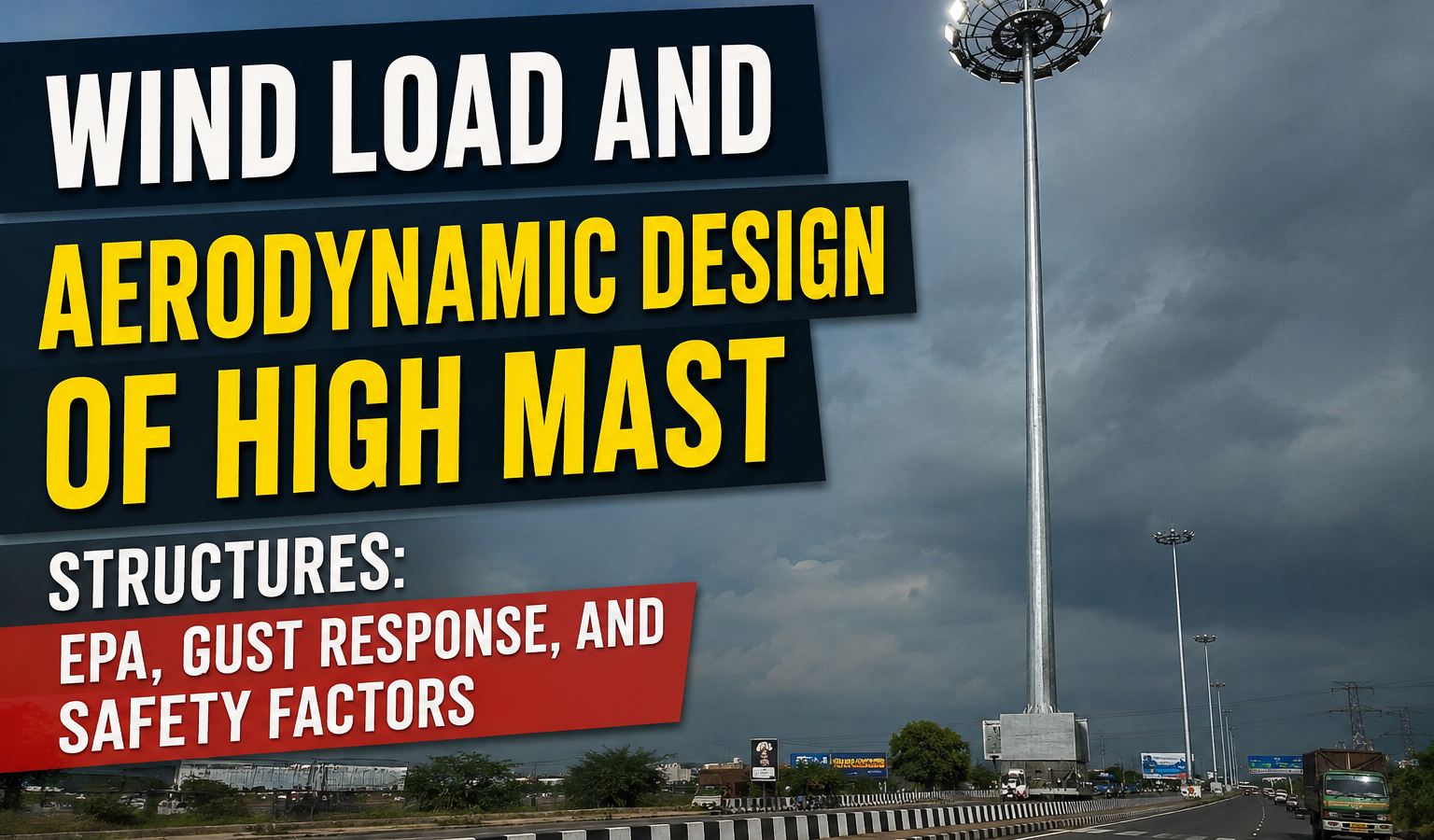
At 30-40 metres of height, a high mast pole is a slender, flexible cantilever whose worst enemy isn’t static wind pressure but dynamic gust response and vortex shedding. A structure that comfortably passes a static wind-pressure check on paper can still develop fatigue cracks within a few years if its dynamic behaviour under real, turbulent wind was never properly characterized Wind Load and Aerodynamic Design of High Mast Structures.
This section covers how engineers calculate effective projected area, account for aerodynamic instability at extreme heights, and set the overturning safety margin that keeps a fully loaded headframe upright through a design-basis storm — and why these three checks are interdependent rather than separate line items in a design report.
Wind engineering for high mast structures sits at an unusual intersection of structural design and dynamics that many otherwise competent structural engineers encounter infrequently, since most building and bridge design work doesn’t demand the same close attention to vortex shedding and gust response that a slender, 30-40m cantilevered pole requires. Reviewing a high mast wind design with this in mind — checking not just whether the static strength calculation looks reasonable, but whether the dynamic response checks were performed at all — is a worthwhile due-diligence step for any project owner relying on an unfamiliar design consultant.
Calculating Effective Projected Area (EPA) of the Headframe Assembly
Effective Projected Area (EPA) is the wind-facing surface area of the entire headframe — luminaires, mounting brackets, the pulley housing, and the ring structure itself — used to calculate total wind force via F = 0.5 × ρ × V² × Cd × EPA, where ρ is air density, V is design wind speed, and Cd is the drag coefficient of the assembly shape Wind Load and Aerodynamic Design of High Mast Structures.
Because luminaire fixtures and brackets are irregular shapes, EPA is usually derive summing the project area of each component at its worst-case orientation to the wind, then applying a shielding or shape factor rather than treating the headframe as a single solid plate — over-simplifying this step is one of the most common under-design errors in headframe load calculations, because a headframe with 6-8 luminaires mount radially presents a very different effective area to wind approaching from different directions.
A further complication: as fixtures age and are retrofit (see Cluster 29), the EPA of an in-service headframe can change substantially from its original design assumption — replacing older, bulkier HID fixtures with slimmer LED luminaires generally reduces EPA and is beneficial, but adding supplementary equipment (CCTV, wireless gateways, additional signage) to an existing headframe without re-checking EPA is a common and under-recognize source of latent overstress on ageing structures.
Dynamic Gust Response and Vortex Shedding at Height
Static wind pressure calculated per IS 875 Part 3 (or ASCE 7 for international projects) is only the starting point. At 30m+, the pole’s natural frequency can fall into a range where vortex shedding — periodic alternating pressure from wind separating around the pole shaft — excites cross-wind oscillation, sometimes at wind speeds well below the design gust speed used for the static strength check.
Design codes address this through a gust effect factor (Gf) applied to the along-wind static pressure, and separately through fatigue-category checks on welded details (particularly the base flange weld) against the cumulative cycles of vortex-induced low-amplitude oscillation over the structure’s service life — a fatigue check that is entirely independent of, and often more governing than, the ultimate strength check under peak wind.
Poles with unfavourable natural frequency relative to expected shedding frequencies sometimes require tuned mass dampers mounted inside the shaft near the tip, or perforated/spoiler fittings that disrupt the regular vortex formation pattern along the shaft’s length. The practical warning sign of this problem in the field is a pole that visibly sways or hums audibly in moderate, steady wind — a symptom worth investigating structurally rather than dismissing as a curiosity.
Fatigue Category and the Base Flange Weld
The base flange-to-shaft weld is almost always the fatigue-critical detail on a high mast pole, both because it carries the full bending moment from the entire structure above and because a full-penetration circumferential weld inherently has some level of geometric stress concentration at its toe. Fatigue design categorizes this detail (per AASHTO fatigue provisions or equivalent) and checks it against the expected number of stress cycles over the design life — a check that becomes governing, rather than the static strength check, on masts in regions with frequent moderate winds capable of exciting vortex-shedding oscillation even without ever approaching design ultimate wind speed Wind Load and Aerodynamic Design of High Mast Structures.
Structural Safety Factor Against Overturning
Overturning safety factor compares the stabilizing moment (foundation weight plus soil resistance) against the overturning moment from peak wind load at the base. Most codes and utility specifications require a minimum factor of safety of 1.5-2.0 against overturning under the design return-period wind (commonly 50-year or 100-year return period depending on structure importance category and consequence of failure).
This overturning check is fundamentally a geotechnical-structural interface calculation — it depends as much on accurate soil bearing and foundation design (covered in Cluster 18) as on the wind load itself, which is why a wind load calculation performed in isolation from an actual site-specific soil investigation carries real risk of an inadequate final safety margin, even if every individual number in the calculation chain looks correct on its own.
Regional Wind Zone Variation and Design Wind Speed Selection
India’s wind loading code divides the country into multiple wind zones with basic wind speeds ranging from roughly 33 m/s in the calmest interior regions to 55-50 m/s along the most cyclone-exposed sections of the eastern and western coastlines. A high mast design import unchange from a lower wind zone project into a coastal or cyclone-prone zone — a surprisingly common shortcut when standard drawings are reuse across a state-wide tender rather than re-verifie per site — can leave a structure with dramatically less margin than the local wind climate demands.
Basic wind speed from the code map is only the starting point; actual design wind pressure also incorporates terrain category (open coastline versus sheltered urban terrain behaves very differently), height above ground (wind speed increases with height following a defined profile), and a topography factor for masts sited on hills, ridgelines, or other locally wind-accelerating terrain features. Each of these multipliers can materially change the final design pressure from the basic zone wind speed alone.
Given how much of the overturning safety margin traces back to this single input, site-specific verification of wind zone, terrain category, and topography factor — rather than relying on a generic ‘standard design’ pole regardless of exact location — is one of the highest-value engineering reviews available relative to its cost on any high mast project spanning multiple sites.
Practical Field Best Practices
- Never estimate headframe EPA as a flat percentage of ring diameter — sum actual component projected areas.
- Check natural frequency against local vortex-shedding wind speed range for masts above 25-30m.
- Apply the code-mandated gust effect factor; static pressure alone under-designs for dynamic response.
- Confirm overturning FoS meets or exceeds 1.5-2.0 at the specified return-period wind speed.
- Re-check EPA after any headframe retrofit or equipment addition, not just at original design.
- Investigate any audible humming or visible sway in moderate wind as a potential vortex-shedding symptom Wind Load and Aerodynamic Design of High Mast Structures.
Summary Checklist
- EPA calculated component-by-component, not as a flat estimate.
- Gust effect factor and vortex-shedding fatigue check applied per code.
- Overturning safety factor ≥1.5-2.0 verified against foundation and soil data.
- Natural frequency reviewed against site-specific wind spectrum for tall masts.
- Base flange weld fatigue category checked against expected service-life stress cycles.
- EPA re-verifie whenever headframe equipment is add or fixtures are retrofit.